 Indoor transformer installations
Transformers installed interior to a building require special consideration for their placement because of the potential hazard should a catastrophic failure occur. The objective of the following rules is the practical safeguarding of people and property.
Less-flammable liquid-insulated transformers. The specific NEC requirements for these transformers can be found in Sec. 450-23. Transformers qualifying for placement in this category must contain a liquid with a fire point not less than 300 [degrees] C. The flow chart in Fig. 1 (on page 75) describes an overview of the requirements for this section.
Nonflammable fluid-insulated transformers.The specific NEC requirements for these transformers can be found in Sec. 450-24. Transformers in this class must have a nonflammable dielectric fluid that does not have a flash or fire point and is not flammable in air. The flow chart in Fig. 2 describes the requirements for this section.
Askarel-insulated transformers. NEC requirements for these transformers can be found in Sec. 450-25. Transformers in this class are insulated with Askarel fluid. If the transformer is rated over 25 kVA, it must be provided with a pressure-relief vent. If installed in a poorly ventilated area, the transformer must be provided with a method to absorb any gases generated by arcing inside the case, or the pressure relief vent must be vented to the outside of the building.
As with less- and non flammable liquid-filled transformers, those filled with Askarel are not required to be installed in a vault unless rated greater than 35kV. The requirements in this section have remained unchanged for many years, since no new installations have been made in recent years.
Oil-insulated transformers. The specific NEC requirements for these transformers can be found in Sec. 450-26. In general, these transformers always must be installed in a vault. Exceptions to the vault requirements are as follows.
* If the total transformer capacity is 112 1/2kVA or less, the vault may be constructed of 4-in. reinforced concrete.
* If the nominal voltage is 600V or less, the vault may be omitted if arrangements are made to prevent a transformer oil fire from igniting other materials, and the total transformer capacity does not exceed 10kVA in a section of a building classified as combustible or 75kVA in a section of a building classified as fire-resistant construction.
* Electric furnace transformers can be installed without a vault where the total rating does not exceed 75kVA, and arrangements are made to prevent a transformer oil fire from igniting other materials. These transformers are very specific to applications involving electric furnaces, and since many precautions must be taken for the electric furnace itself, the vault requirement is relaxed.
* Transformers are permitted to be installed in a detached building that does not comply with the vault requirements if neither the building nor its contents presents a fire hazard to any other building or property, and if the building is used only in supplying electric service, and the interior is accessible only to qualified persons.
* The vault may be omitted for transformers used in portable and mobile mining equipment with additional conditions specified.
(by Loyd, Richard E)
to be continue...
 Knowing NEC, NESC, insurer, and listing agency installation requirements will help you select the best type of insulating medium for the application.
Increasing concerns over fire safety in and around buildings can result in questions about transformer installations, specifically for liquid-filled transformers. Also, installation requirements per the National Electrical Code (NEC) and the National Electrical Safety Code (NESC) as well as insurer and listing requirements can influence your decision as to the type of transformer specified. The following will answer these questions and help you make informed decisions.
A variety of requirements may be applied to a transformer installation, but each one must be considered for the application. We'll focus our attention on the following:
* The NEC (1993 and 1996 editions), which is generally enforced by local authorities responsible for building and/or electrical codes;
* Listing requirements, which are based on third-party evaluation of the transformer or components and are specific to the product and manufacturer;
* Insurer requirements, since the failure of a transformer can result in property damage, loss of life, and loss of revenue (due to downtime) for the business affected by the failure; and
* Local amendments, which the local code enforcing body may have adopted, additional requirements above and beyond the basic installation Code.
Transformer installation requirements in the 1993 NEC
In order to evaluate the specifics of NEC requirements on transformer installations, you should review the requirements for each transformer type. To show the differing requirements related to various transformer types, we'll cover the specifics for less-flammable liquid-, non flammable liquid-, Askarel-, and oil-filled transformers.
Vaults. In determining the type and location of a transformer in a design, the requirement to have a transformer vault plays a key role in the cost and safety of an indoor installation. The expected construction costs and space impacts of a vault must be considered before selecting the particular transformer to use. So that you can understand the magnitude of the vault issue, the following requirements for transformer vaults are summarized from Part C of Article 450 in the NEC.
Walls, roofs, and floors shall be constructed of materials providing a minimum fire resistance rating of 3 hrs. Typical of this rating is 6-in.-thick reinforced concrete.
Floors in contact with the earth shall be 4-in.-thick concrete minimum. If located with space below, the floor shall have structural strength for the expected load and have a fire resistance rating of 3 hrs.
Doorways leading to the interior of a building from the vault shall have a 3-hr construction. A door sill or curb must be provided that will confine the oil from the largest transformer within the vault. Minimum sill height is 4 in.
Doors shall be equipped with locks and accessible only to qualified personnel. Doors shall swing out and be equipped with panic bars, pressure plates, or other devices that are normally latched.
Ventilation (per specifics in Sec. 450-45): The vault must be ventilated to remove the heat generated by the transformers during operation so as not to create a temperature rise beyond the transformer rating.
Drainage: Vaults containing more than 100kVA of transformer capacity shall be provided with a drain or other means that will carry off any accumulation of oil or water in the vault unless local conditions make this impracticable. The floor shall be pitched to the drain where provided.
Note: If the transformer is protected with an automatic sprinkler, water spray, carbon dioxide, or halon, the entire vault construction is permitted to be of a 1-hr rating.
As you can see, there's a substantial investment in construction costs and physical space when a transformer vault is needed. However, by utilizing the following additional safeguards, a vault may not be necessary.
(by Loyd, Richard E)
to be continue...
 7. Precision Top-Ups and Drain and Fills
Once the bulk storage system is properly set up, one should consider the method for transporting oil and filling machines. The best top-up method utilizes a proper top-up container, one that is sealed from the environment, has a built in spout, hand pump, etc. If short cuts are taken at this stage, all of the time and effort spent building and designing the bulk storage system and ensuring the quality of the bulk oil with filtration will have been wasted. Too many times oil is highly contaminated from the time it is dispensed into the top-up container to the time it is added to the machine.
Using washable and re-usable top-up containers allow for easy cleaning and maintenance. Typically, non-sealable top-up containers that are re-used introduce large amounts of containments to the system, which could counteract any effort of removing or excluding contaminants, and also can have a slight lubricant cross-contamination effect.
For top-ups of larger sump volumes, such as large gearboxes, circulating system reservoirs, etc., the use of filter carts is the preferred method for transferring the new oil from the storage container to the machine.
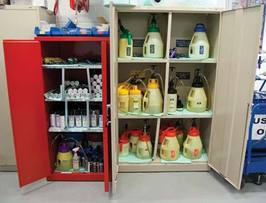
8. Proper Top-Up Container and Grease Gun Storage
Storage for top-up containers, grease guns, rags, etc., is another important step to ensure contaminants are not introduced to the lubricants as a result of poor housekeeping. These tools should have their own dedicated fire-proof storage cabinets for easy access and organization.
Grease storage is simpler than oil storage but also must not go overlooked. Open grease tubes and drums are magnets for attracting airborne contaminants such as lint and dust. Securing used grease tubes that will be re-used in sealable washable containers is considered the best practice. The containers will hold one tube of grease and allow for great contaminant exclusion. Used drums of grease are at an even higher risk of contamination. These drums are often opened and used over a greater period of time, leading to more and more opportunities for contaminants to enter. If not using a sealed air style grease dispensing unit for drums of grease to fill grease guns, some of the best methods for contaminant exclusion are to use Velcro style covers or snap-on caps. Using these types of contaminant exclusion devices will keep the grease cleaner and prolong its life.
Grease guns should be stored in a clean, dry and controlled environment. They are precision tools that must be taken care of in order for them to provide the maximum degree of accuracy and reliability. Grease guns should be regularly cleaned and inspected for proper function and an annual calibration should be performed. This calibration will ensure the same volume of grease is still being dispensed with one shot as when the gun was new. The best method for grease gun calibration is to use a postal scale to measure how much grease is dispensed with one pump.
Lubrication tools should be stored in a fire-proof storage cabinet for easy access and organization.
(by Stephen Sumerlin)
to be continue...
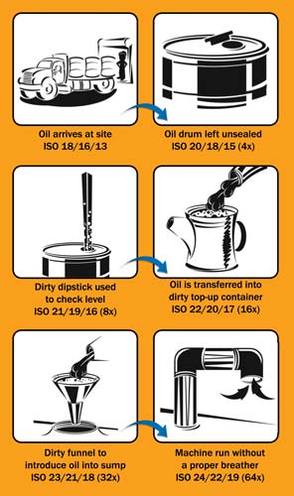 3. New Oil Receiving Oftentimes, improper receiving techniques do nothing but promote higher risks of contamination ingression, mixing of lubricants, etc. Proper written receiving procedures should be in place to ensure the highest level of consistency and cleanliness is maintained. Proper receiving techniques should include filtration of incoming oils. Many times new oils may be dirtier than your defined particle target cleanliness level. Meaning, if you define your particle target cleanliness level and spend time, money, manpower, etc., to achieve these levels of in-service lubricant cleanliness, the last thing you want to do is contaminate it with “dirty” new oils. 4. Quality Control Quality control of lubricants delivered from lube suppliers must be verified to ensure the correct product is being delivered and that the cleanliness of the delivered lubricant are up to current target particle and moisture cleanliness levels. To help ensure your lubricants are meeting their standards, the use of oil analysis is a powerful tool and will reveal the following: - Quality of base stocks
- Additive quality and concentration
- Lubricant performance properties
- Thickener performance properties (grease)
5. Presence of Mixed or Contaminated Lubricants Oil analysis results and other quality assurance variables, such as damaged containers, rusted containers and any other quality issue, should be well documented and cataloged. Items to note in the documentation phase are: - Delivery date and date of oil sample taken
- Inspection results of storage containers
- Labels depicting results of oil analysis test
- Itemized checklist for sampling test
- Periodic decontamination with filtration
Whichever storage container is chosen, it is best to filter the new oil while filling the storage container. Doing so will reduce the amount of contamination that is delivered with the new oil, but periodic filtration and agitation should be performed to maintain certain ISO cleanliness levels and prevent additive settling. Periodic filtration is a good practice to ensure clean, fresh oil will be used to perform top-ups and drain and fills. There are two primary methods for filtration of bulk stored oils: hard plumbed filtration system or filter cart. The hard plumbed filtration system works best in conjunction with a rack mounted system. Each container should be fitted with a breather, sight glass, filter, lubricant label, quick connect fittings and dedicated dispensing line. This system will help ensure the lubricants are at optimal condition when they are needed and the right product for the application is dispensed. Periodic filtration for drum storage also is easy with the use of a filter cart once the drums are equipped with quick couplers. No matter how large or small the storage container, periodic decontamination should be a priority to maintain the quality of the stored lubricant. 6. Dispensing Options for Stored Oils When stored oil is transferred from the bulk storage system to the top-up container, it is best to filter the dispensing oil. This can be made very easy with the use of a hard plumbed filtration system and a rack mounted storage system fitted with dedicated dispensing nozzles. If using 55-gallon drums, they can be fitted with quick connect fittings, a hand pump, an inline filter manifold breather and sight glass to achieve the same goal. Improper dispensing of new oils into top-up containers is a primary cause of self-induced contamination. Proper techniques and tools must be used to ensure your new, filtered oil is transferred to the top-up container with minimal exposure to atmospheric conditions. Not using proper techniques here could be a waste of time to the filtration efforts, storage and in-service lubriation cleanliness. (by Stephen Sumerlin) to be continue...
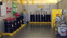 For a complete and proper lubrication program to work effectively and provide the most return on investment, the entire gamut of lubrication must be considered, ranging from receiving to application. Through this gamut there are missed opportunities to increase equipment productivity and reliability and to maximize the returns of investing in a professionally designed lubrication program. One of the biggest and most costly missed opportunities is proper lubricant storage and handling. Many facilities are unaware of the danger improper lubricant storage and handling practices create and what inevitable fate it can lead to in terms of equipment reliability and lifecycles. Proper lubrication is not only about the right amount-at the right time-at the right place, it is also about keeping lubricants clean, cool and properly identified. Here are some tips to help outline the best practices for proper lubrication storage and handling: 1. Lube Room Design and Requirements A properly designed lube room must be functional, safe and expandable, and provide all necessary storage and handling requirements for the facility. Lube room designs should allow the maximum storage capacity without allowing for too much bulk oil and grease storage. Limiting the amount of bulk oil and grease storage will allow the oils that are stored to be used in a timely manner. Some key features to consider are a limited access door, which will allow for logging of who and when a lube technician enters and leaves the room; visible landing area for new lubricants; log all new lubricant deliveries; make filtration of stored lubricants easy; provide proper safety devices; designate enough floor space for fire proof storage cabinets to store top-up containers, grease guns, etc.; and include a desk and computer to track inventory, sampling, filtration, receiving, etc. It also is a smart idea to have a separate storage area to store bulk totes, drums, buckets, etc. 2. Bulk Oil Storage The first area of a lubricant storage and handling system that requires attention is bulk storage. Whether storing lubricants in a 10,000-gallon tank or 55-gallon drums, it is very important to ensure the lubricants’ quality is not tainted by contamination or additive settling. To help ensure lubricants stay in an optimal condition, one must determine how much lubricant should be stored at one time. To aid in this process, certain steps can be employed, such as: - Determine lubricant consumption rate. Consumption will vary greatly depending on industry and equipment type. To ensure the right quantities of lubricants are being stored at a facility, the consumption rate must be determined. There are many factors that contribute to consumption, ranging from leaks to excessive drain and fills.
- Determine lubricant storage capacity. The required lubricant storage capacity depends on consumption, but often there are too little or too many lubricants stored at one time. The proper storage capacity should maximize shelf life but allow for a certain percent excess of critical lubricants to be stored for emergency situations.
- Determine lubricant supplier turnaround time. A lubricant supplier’s turnaround time should be a metric used to aid in determining the quantity of lubricants stored. If there is a short time interval between deliveries, fewer lubricants can be stored onsite, but if there is a lengthy time interval between deliveries, the quantity of lubricants stored onsite should account for this.
Once the consumption rate and storage capacity have been determined, one should decide what type of storage containers will be used. The correct size storage container is a direct reflection of the consumption rate and storage capacity. If a large consumption rate is determined, a large bulk storage tank may yield the best results, but if a low consumption rate is determined, a rack mounted storage system or 55-gallon drums may yield the best results. For smaller facilities that have a small consumption rate, the use of drum storage may be the best option (by Stephen Sumerlin) To be continue...
 "Our oil analysis results often show levels of water present in the oil. We are considering the purchase of portable equipment suitable for the removal of water from lube and hydraulic oil systems. I have also been told by some people that some separators can only remove water down to the water saturation level of the oil. Is there a preferred method for removing water from oil in a lube or hydraulic circulating system? How much water can be removed by these methods?"Water in any lubrication system is bad news. In hydraulic systems, it can result in vaporous pump cavitation, corrosion and valve stiction, while in circulating lube oil systems it can cause oil film strength loss, rusting and other serious mechanical problems. The effects of water on the oil are often overlooked. Excessive water contamination can result in premature oil oxidation and promote the buildup of sludge and varnish. In ester-based fluids, it can result in the hydrolytic destruction of the base fluid resulting in the formation of corrosive acids. In some circumstances, water can also strip additives from the oil through water washing or hydrolysis resulting in premature oil degradation. For these reasons, the best strategy when it comes to water is to monitor and control the root cause of the water ingression. This can be achieved by ensuring that all seal and breathers are in good shape (consider using desiccant style breathers), lube tank hatches are closed and sealed properly and that top-up oil is stored and handled properly. Water can exist in three phases in an oil, free, emulsified and dissolved. Free and emulsified water cause the most damage so a good rule of thumb is to keep moisture levels below the saturation point so that all the water is in the dissolved state. For typical mineral-based industrial oils, this is typically 200-300 ppm. The most effective way of achieving this is to use a vacuum dehydration unit. These systems are capable of removing free and emulsified water as well as up to 70-80% of the dissolved water. For a typical hydraulic fluid, this can mean water levels as low as 30-50 ppm (0.003-0.005%). Alternatively, many companies are reporting success with vapor extraction devices mounting on tank tops. Some of these devices work similar to air conditioners in removing humid air from tank headspaces.
|

 RSS Feed


