There are several jobs that the lube oil is designed to perform. Lubrication of moving parts, cooling, cleaning, corrosion control, and etc. The oil companies work diligently to produce oils to meet engine manufacture's ever increasing requirements, creating better and better oils each year. Over the years, using vastly improved oils, the engine manufacture's have increased their recommended oil drain intervals for their engines, but we are still draining the oil on a routine basis. When most maintenance personnel are asked, "why does one have to change the oil?" Their answer is usually one of the following: "Because it breaks down" or " Because it wears out."
The concept that oil "breaks down" or "wears out" is not correct. Just look at what has happened over the past fifteen years, in regards to oil drain intervals. Fifteen years ago, typical recommended oil drain intervals for a 300 horsepower H.D. diesel was around 8,000 to 10,000 miles in an over the road truck. Today, the same trucks typically have 425 to 450 horsepower engines, yet the oil drain intervals have increased to 15,000 to 25,000 miles. The same quality crude oil base stocks that were used 15 years ago are used to make oils of today. So why does the same oil today last twice as long as it did fifteen years ago? The answer can be found within the additive package of today's oil. The petroleum base of oil lube does not wear out, rather it is the additives within the oil that become depleted, due to the presence of contamination. Therefore, it makes common and technical sense that if one could remove these contaminants, we could then run the oil for a longer period of time, but for how long?
New Engines - New Problem:
One of the major contaminants facing the new oils of today is Soot contamination. Soot is a four letter word to diesel engines. In recent years engine manufacturers have had to develop engines to meet EPA emission standards. Therefore, contamination that once was "Going Up In Smoke," is remaining in our engines and winding up in the lube oil. These newer engines emit less contamination through the exhaust, therefore higher carbon soot levels are being detected within the engine. Several SAE papers have shown how Soot contributes to diesel engine wear. One of these papers points out just how severe the problem of Soot in today's engines is. According to COMO paper EX1, Soot will enter the lubrication oil at the rate of .0048 oz for every gallon of fuel burned. A truck will burn 1,786 gallons of fuel every 12,500 miles, at 7 mpg. During this 12,500 mile interval, more than half a pound (8.75oz) of Soot will enter the oil.
The majority of Soot particles generated within the engine are 10 microns or SMALLER. Most engines are only equipped with full flow filters that, at best, remove and control particles 15 microns and LARGER. Full flow filters are now designed to protect the engine from large particles that could damage vital parts. These filters must be porous enough to allow high flow rates of oil to the engine for lubrication of parts. The typical flow rate for a full flow filter within a diesel engine is 15 to 20 quarts per minute. Therefore, they are not designed to remove small contamination. Full flow filters do little to control Soot contamination within the oil.
Soot & The Next Millennium:
This problem of Soot contamination in today's engines will soon become a larger problem by the year 2004. EPA emission requirements for the year 2004 will force the diesel industry to deal with a three letter word, EGR (exhaust gas re-circulation). In March 1998, at API's Lubricants Committee meeting in San Francisco , as reported in "Lubes & Greases" magazine (May '98), John Graham of Cummins Engine Co. had the following comments about the impact of EGR on diesel: "Diesel engine manufacturers face the prospect of having to REDUCE their drain interval recommendations significantly because of increasing levels of Soot, caused by the need to introduce EGR." In an effort to reduce nitrogen oxide (NOx) emissions in the year 2004, it will be necessary to incorporate EGR for diesel engines. EGR exhaust is cooled and re-circulated though the engine in order to reduce oxygen concentrations within the cylinder thereby lowering flame temperature and nitrogen oxide (NOx). Soot and fuel sulfur oxides are critical issues with EGR. In his opinion, Graham noted a dramatic decrease in oil change intervals to, say, around 10,000 miles would be needed. Instead of trying to solve this problem of higher Soot levels by adding additional filtration, the engine manufacturers and oil companies are relying on those "NEW" oils to solve this problem and if the oil companies can come up with new oils to contend with EGR Soot, the only option will be to shorten oil drain intervals, or is this the only option?
There is a very common sense approach to the dilemma facing the engine and oil manufacturers. Soot is not a gas or liquid, it is a solid particulate. One can greatly extend present routine lube oil drains by installing additional depth type by-pass filters. The By-Pass Oil Filter only filters about 10% of the oil each minute through a very dense element. It does not supply the engine with oil for the purpose of lubrication. Its sole purpose is to clean the oil. By-Pass filters can control the higher levels of Soot and other solid Contamination within today's engines, as well as ones into the future, without the need to go to a higher tech oil.
Other than Soot , there are several other types of contamination that must be dealt with in order to extend lube oil drains. In order to greatly extend and/or eliminate the process of routine oil drains one must install additional filtration and establish the proper service intervals for these filters to deal with contamination missed by the full-flow filters and other types of contamination generated within the engine.
There are three basic types of contamination that must be dealt with: "Solid", "Moisture" and "Condition Caused" contamination. The following information will fully explain these types of contamination and how additional By-Pass filtration will effectively control these areas.
Soot and Other Solid Contamination: It is generally recognized, backed by numerous tests and studies over the last 40 years, that contamination generated in an engine that is responsible for the majority of "normal" wear, is within the 1 - 15 micron range. Also this small solid contamination contributes to accelerating Condition Caused Contaminants such as Oxidation, Nitration, Acid formation and more. Consequently, it is imperative that this contamination be removed from the system as fast as possible. The typical factory full-flow filter cannot control 1-15 micron particles due its porous design to supply the engine with a high flow rate of oil. One must use UF filtration that is capable of controlling solids in the 1-15 micron ranger and smaller.
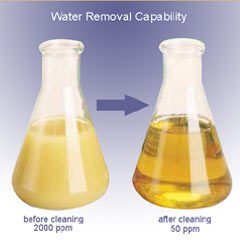
Moisture Contamination: Moisture contamination within the lube oil will cause viscosity increase, VI polymer decrease, TBN decrease, acid formation, accelerated sludge formation, and corrosion of parts. To safely eliminate routine oil drains, one must use additional filtration that utilizes an adsorbent filter media which can remove suspended moisture from the lube oil.
Condition Caused Contamination: There are three MAJOR Condition Caused Contaminations that are formed within the lube oil during normal use: Oxidation, Nitration, and Acid. These contaminants are formed when solid and moisture contamination are present, and certain operating conditions exist within the engine. These Condition Caused Contaminants can be controlled by the use of additional filtration and adding new make-up oil at the service of the UF by-pass filter.
There are three basic types of contamination that must be dealt with: “Solid”, “Moisture” and “Condition Caused” Contamination. The following information will fully explain these types of contamination and how adding additional By-Pass filtration will effectively control these areas.
a) Oxidation: Oxidation occurs when the hydrocarbon constituents (and other products) of lube oil combined chemically with oxygen. Lube oil in engines will combine with available oxygen under certain conditions to form a wide variety of oxidation products. Many of these direct or primary oxidation products combine with other materials such as wear metals, solid contamination, and moisture, to form second and third derivative products. As with most chemical reactions, oil oxidation is accelerated by heat and pressure. Heat in particular will speed up the oxidation process. Various studies have shown that lube oxidation (with many variables such as the type lubricant and additive package in the lubricant) that the oxidation rate can be doubled for every 15 to 20 degrees increase over 180 degrees F. Also, engine load, which will dictate the levels of oxygen and pressure within the engine can be seen in the form of accelerated acid formation, corrosion, oil thickening, deposit formation, and accelerated wear.
All top quality lube oils have an additive package that contains oxidation inhibitors to slow the oxidation process and alkaline detergents that will neutralize acids formed by oxidation. Normally these additives will only last a certain length of time before they are depleted and the oil must be drained. GCF, Inc. has established the correct means by which to control oxidation within engines. As we have seen, oxidation is greatly stimulated by the contamination solids and moisture. Solids tend to hold heat, thereby increasing the lube oil temperature around the solid contamination. This condition acts to accelerate oxidation. Combine this effect with the presence of moisture (H2O) from normal condensation, and the oxidation process accelerates even faster. When moisture is present in the lubrication system, the level of oxygen available to mix with hydrocarbons in the lube oil is raised dramatically. The presence of normal solid and moisture contamination, combined with maximum operating load of the equipment, will produce high oil oxidation rates, even with normal oil temperatures. In order to control the oxidation process, the GCF PM Program recommends By-Pass filtration products that can control the levels of moisture, wear metals and other solid contamination. By removing this contamination, the oil will offer a better seal between the rings and liners and therefore reduce the amount of blow-by during the combustion process. Blow-by contributes to the amount of oxygen and moisture within the engine.
Once we have removed the contamination which acts as catalyst to accelerate the oxidation process and have offered a cleaner oil to seal the engine, then we are left with MINIMAL OXIDATION for the additive package of the oil to contend with. The engine will use a certain amount of oil each operating day. Combine this amount of new oil with the amount added at the time the By-Pass Filter is serviced, and the engine will maintain a sufficient amount of active additives to keep oxidation in check indefinitely.
b) Nitration: The combustion chambers of engines provide one of the few environments where there is sufficient heat and pressure to break the atmospheric nitrogen molecule down to two atoms that can react with oxygen to form nitrous oxides (NOx). When nitrogen oxide products enter the lube oil through normal blow-by, they react with moisture present in the lube and become very acidic and rapidly accelerate the oxidation rate of the oil. Proper By-Pass Filters can control the effects of nitration in the same ways it controls oxidation. By delivering cleaner oil to offer as a seal between the ring and liner, blow-by of NOx components are kept to a minimum. Also, the GCF Filter keeps the oil chemically dry and prevents the mixing of NOx and moisture, which controls NOx acid formation and accelerated oxidation of the oil.
c) Acid Formation: Acids are formed within the lube by several sources. We have already covered two of them in the form of acids formed from oxidation and nitration. In most all forms of fuel for internal combustion engines, trace amounts of sulfur are present. Sulfuric acid is formed within the lube oil when sulfur molecules react with oxygen in the combustion chamber to form sulfur oxides. These sulfur oxides are then blown past the rings and enter the oil. Here the sulfur oxides mix with moisture to form the highly corrosive sulfuric acid. It is next to impossible to remove trace amounts of sulfur from fuels by filtration. However, it takes two components to make the sulfuric acid, sulfur oxides and water. By using UF By-Pass filters that utilize absorbent type filter media, such as cellulose (paper) or cotton, the TBN (Total Base Number) of the oil stays up and the TAN (Total Acid Number) remains low.
After taking a look at all of the types of contamination and the effects they can have on an engine if left unchecked, I think that you can now see why the use of UF By-Pass filters is so important. When using these filters, one can remove and control contamination within the engine. Once this contamination is removed from the system, lube oil drain intervals can be greatly extended.
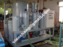
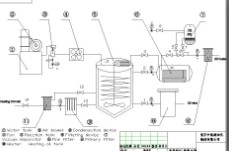
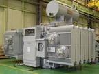
After understand above facts, we recomend our TYA vacuum lube oil purifier machine, which can solve the oil "wear out" problem, it is more economical compare with replacing new lube oil, because oil cost is higher everyday.
The concept that oil "breaks down" or "wears out" is not correct. Just look at what has happened over the past fifteen years, in regards to oil drain intervals. Fifteen years ago, typical recommended oil drain intervals for a 300 horsepower H.D. diesel was around 8,000 to 10,000 miles in an over the road truck. Today, the same trucks typically have 425 to 450 horsepower engines, yet the oil drain intervals have increased to 15,000 to 25,000 miles. The same quality crude oil base stocks that were used 15 years ago are used to make oils of today. So why does the same oil today last twice as long as it did fifteen years ago? The answer can be found within the additive package of today's oil. The petroleum base of oil lube does not wear out, rather it is the additives within the oil that become depleted, due to the presence of contamination. Therefore, it makes common and technical sense that if one could remove these contaminants, we could then run the oil for a longer period of time, but for how long?
New Engines - New Problem:
One of the major contaminants facing the new oils of today is Soot contamination. Soot is a four letter word to diesel engines. In recent years engine manufacturers have had to develop engines to meet EPA emission standards. Therefore, contamination that once was "Going Up In Smoke," is remaining in our engines and winding up in the lube oil. These newer engines emit less contamination through the exhaust, therefore higher carbon soot levels are being detected within the engine. Several SAE papers have shown how Soot contributes to diesel engine wear. One of these papers points out just how severe the problem of Soot in today's engines is. According to COMO paper EX1, Soot will enter the lubrication oil at the rate of .0048 oz for every gallon of fuel burned. A truck will burn 1,786 gallons of fuel every 12,500 miles, at 7 mpg. During this 12,500 mile interval, more than half a pound (8.75oz) of Soot will enter the oil.
The majority of Soot particles generated within the engine are 10 microns or SMALLER. Most engines are only equipped with full flow filters that, at best, remove and control particles 15 microns and LARGER. Full flow filters are now designed to protect the engine from large particles that could damage vital parts. These filters must be porous enough to allow high flow rates of oil to the engine for lubrication of parts. The typical flow rate for a full flow filter within a diesel engine is 15 to 20 quarts per minute. Therefore, they are not designed to remove small contamination. Full flow filters do little to control Soot contamination within the oil.
Soot & The Next Millennium:
This problem of Soot contamination in today's engines will soon become a larger problem by the year 2004. EPA emission requirements for the year 2004 will force the diesel industry to deal with a three letter word, EGR (exhaust gas re-circulation). In March 1998, at API's Lubricants Committee meeting in San Francisco , as reported in "Lubes & Greases" magazine (May '98), John Graham of Cummins Engine Co. had the following comments about the impact of EGR on diesel: "Diesel engine manufacturers face the prospect of having to REDUCE their drain interval recommendations significantly because of increasing levels of Soot, caused by the need to introduce EGR." In an effort to reduce nitrogen oxide (NOx) emissions in the year 2004, it will be necessary to incorporate EGR for diesel engines. EGR exhaust is cooled and re-circulated though the engine in order to reduce oxygen concentrations within the cylinder thereby lowering flame temperature and nitrogen oxide (NOx). Soot and fuel sulfur oxides are critical issues with EGR. In his opinion, Graham noted a dramatic decrease in oil change intervals to, say, around 10,000 miles would be needed. Instead of trying to solve this problem of higher Soot levels by adding additional filtration, the engine manufacturers and oil companies are relying on those "NEW" oils to solve this problem and if the oil companies can come up with new oils to contend with EGR Soot, the only option will be to shorten oil drain intervals, or is this the only option?
There is a very common sense approach to the dilemma facing the engine and oil manufacturers. Soot is not a gas or liquid, it is a solid particulate. One can greatly extend present routine lube oil drains by installing additional depth type by-pass filters. The By-Pass Oil Filter only filters about 10% of the oil each minute through a very dense element. It does not supply the engine with oil for the purpose of lubrication. Its sole purpose is to clean the oil. By-Pass filters can control the higher levels of Soot and other solid Contamination within today's engines, as well as ones into the future, without the need to go to a higher tech oil.
Other than Soot , there are several other types of contamination that must be dealt with in order to extend lube oil drains. In order to greatly extend and/or eliminate the process of routine oil drains one must install additional filtration and establish the proper service intervals for these filters to deal with contamination missed by the full-flow filters and other types of contamination generated within the engine.
There are three basic types of contamination that must be dealt with: "Solid", "Moisture" and "Condition Caused" contamination. The following information will fully explain these types of contamination and how additional By-Pass filtration will effectively control these areas.
Soot and Other Solid Contamination: It is generally recognized, backed by numerous tests and studies over the last 40 years, that contamination generated in an engine that is responsible for the majority of "normal" wear, is within the 1 - 15 micron range. Also this small solid contamination contributes to accelerating Condition Caused Contaminants such as Oxidation, Nitration, Acid formation and more. Consequently, it is imperative that this contamination be removed from the system as fast as possible. The typical factory full-flow filter cannot control 1-15 micron particles due its porous design to supply the engine with a high flow rate of oil. One must use UF filtration that is capable of controlling solids in the 1-15 micron ranger and smaller.
Moisture Contamination: Moisture contamination within the lube oil will cause viscosity increase, VI polymer decrease, TBN decrease, acid formation, accelerated sludge formation, and corrosion of parts. To safely eliminate routine oil drains, one must use additional filtration that utilizes an adsorbent filter media which can remove suspended moisture from the lube oil.
Condition Caused Contamination: There are three MAJOR Condition Caused Contaminations that are formed within the lube oil during normal use: Oxidation, Nitration, and Acid. These contaminants are formed when solid and moisture contamination are present, and certain operating conditions exist within the engine. These Condition Caused Contaminants can be controlled by the use of additional filtration and adding new make-up oil at the service of the UF by-pass filter.
There are three basic types of contamination that must be dealt with: “Solid”, “Moisture” and “Condition Caused” Contamination. The following information will fully explain these types of contamination and how adding additional By-Pass filtration will effectively control these areas.
a) Oxidation: Oxidation occurs when the hydrocarbon constituents (and other products) of lube oil combined chemically with oxygen. Lube oil in engines will combine with available oxygen under certain conditions to form a wide variety of oxidation products. Many of these direct or primary oxidation products combine with other materials such as wear metals, solid contamination, and moisture, to form second and third derivative products. As with most chemical reactions, oil oxidation is accelerated by heat and pressure. Heat in particular will speed up the oxidation process. Various studies have shown that lube oxidation (with many variables such as the type lubricant and additive package in the lubricant) that the oxidation rate can be doubled for every 15 to 20 degrees increase over 180 degrees F. Also, engine load, which will dictate the levels of oxygen and pressure within the engine can be seen in the form of accelerated acid formation, corrosion, oil thickening, deposit formation, and accelerated wear.
All top quality lube oils have an additive package that contains oxidation inhibitors to slow the oxidation process and alkaline detergents that will neutralize acids formed by oxidation. Normally these additives will only last a certain length of time before they are depleted and the oil must be drained. GCF, Inc. has established the correct means by which to control oxidation within engines. As we have seen, oxidation is greatly stimulated by the contamination solids and moisture. Solids tend to hold heat, thereby increasing the lube oil temperature around the solid contamination. This condition acts to accelerate oxidation. Combine this effect with the presence of moisture (H2O) from normal condensation, and the oxidation process accelerates even faster. When moisture is present in the lubrication system, the level of oxygen available to mix with hydrocarbons in the lube oil is raised dramatically. The presence of normal solid and moisture contamination, combined with maximum operating load of the equipment, will produce high oil oxidation rates, even with normal oil temperatures. In order to control the oxidation process, the GCF PM Program recommends By-Pass filtration products that can control the levels of moisture, wear metals and other solid contamination. By removing this contamination, the oil will offer a better seal between the rings and liners and therefore reduce the amount of blow-by during the combustion process. Blow-by contributes to the amount of oxygen and moisture within the engine.
Once we have removed the contamination which acts as catalyst to accelerate the oxidation process and have offered a cleaner oil to seal the engine, then we are left with MINIMAL OXIDATION for the additive package of the oil to contend with. The engine will use a certain amount of oil each operating day. Combine this amount of new oil with the amount added at the time the By-Pass Filter is serviced, and the engine will maintain a sufficient amount of active additives to keep oxidation in check indefinitely.
b) Nitration: The combustion chambers of engines provide one of the few environments where there is sufficient heat and pressure to break the atmospheric nitrogen molecule down to two atoms that can react with oxygen to form nitrous oxides (NOx). When nitrogen oxide products enter the lube oil through normal blow-by, they react with moisture present in the lube and become very acidic and rapidly accelerate the oxidation rate of the oil. Proper By-Pass Filters can control the effects of nitration in the same ways it controls oxidation. By delivering cleaner oil to offer as a seal between the ring and liner, blow-by of NOx components are kept to a minimum. Also, the GCF Filter keeps the oil chemically dry and prevents the mixing of NOx and moisture, which controls NOx acid formation and accelerated oxidation of the oil.
c) Acid Formation: Acids are formed within the lube by several sources. We have already covered two of them in the form of acids formed from oxidation and nitration. In most all forms of fuel for internal combustion engines, trace amounts of sulfur are present. Sulfuric acid is formed within the lube oil when sulfur molecules react with oxygen in the combustion chamber to form sulfur oxides. These sulfur oxides are then blown past the rings and enter the oil. Here the sulfur oxides mix with moisture to form the highly corrosive sulfuric acid. It is next to impossible to remove trace amounts of sulfur from fuels by filtration. However, it takes two components to make the sulfuric acid, sulfur oxides and water. By using UF By-Pass filters that utilize absorbent type filter media, such as cellulose (paper) or cotton, the TBN (Total Base Number) of the oil stays up and the TAN (Total Acid Number) remains low.
After taking a look at all of the types of contamination and the effects they can have on an engine if left unchecked, I think that you can now see why the use of UF By-Pass filters is so important. When using these filters, one can remove and control contamination within the engine. Once this contamination is removed from the system, lube oil drain intervals can be greatly extended.
After understand above facts, we recomend our TYA vacuum lube oil purifier machine, which can solve the oil "wear out" problem, it is more economical compare with replacing new lube oil, because oil cost is higher everyday.

 RSS Feed


